Circuit Simulation
Over spring break, I didn’t have tools like an oscilloscope to analyze the circuit like I wanted to, nor did I have the circuit I breadboarded with me. So, I decided to learn how to simulate circuits in LTSpice to allow me to accurately measure properties of the circuit. After watching a couple of tutorials, I got to work.
Astable Multivibrator Simulation
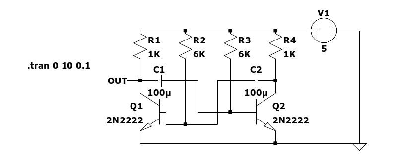
I started by implementing a basic astable multivibrator in LTSpice. I started a transient simulation and attached a voltage probe to the output and, voila… nothing happened.
After probing the internet for solutions, I found one Reddit post that recommended adding the “startup” option to the transient simulation command. From the LTSpice Wiki:
startup: Solve the initial operating point with independent voltage and current sources turned off (but using any constraints specified by a .ic directive). Then start the transient analysis and linearly ramp on these sources during the first 20 us of the simulation.
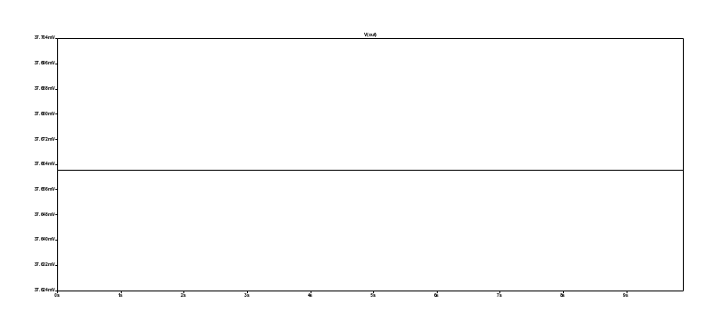
I tried this, but all that changed was that the output voltage started about 10mV higher and then quickly dropped back down to about 37mV as before.
Looking further into the inner workings into astable multivibrators, I learned from this Stack Exchange post that a slight imbalance between the two halves of the circuit is required so that one transistor turns on before the other, thereby starting the back-and-forth cycle. To create this imbalance, I changed R2 from 6K to 5.99K. This worked!
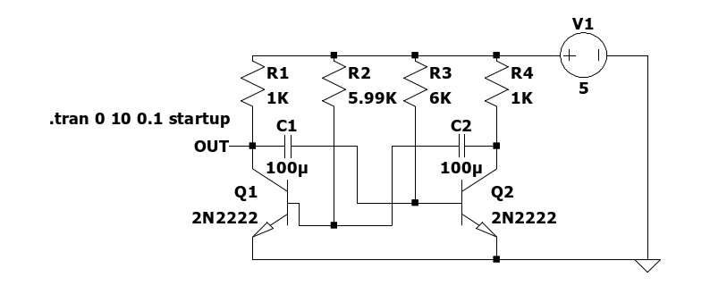
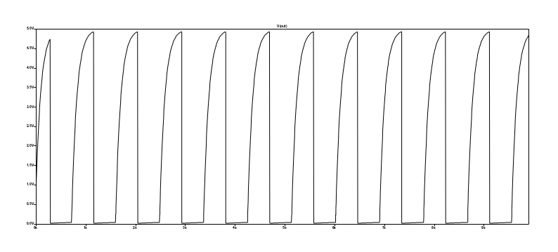
However, on this graph, I measured the frequency to be about 1.13 Hz, corresponding to a BPM of about 68, much lower than the theoretical BPM of 78 that I calculated for the heartbeat circuit with R1 = R4 = 1K ohms, R2 = R3 = 6K ohms, and C1 = C2 = 100 microfarads. This probably indicates that I still need to improve the simulation by modifying some settings, or that I made errors in my calculations.
Full Circuit Simulation
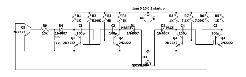
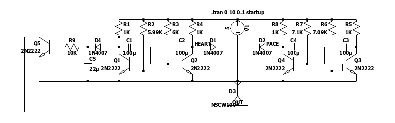
I next recreated the full circuit in LTSpice. Using the “startup” command and creating a slight imbalance in each of the astable multivibrators, I started a transient simulation.
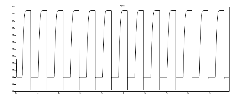
The heartbeat circuit was connected to the output, so the frequency should have been about 78 BPM as calculated. This time, the frequency was 1.31 Hz, or about 78.6 BPM, meaning that the simulation was very close to the expected circuit. Somehow, the frequency changed from 68 BPM when only the heartbeat circuit was present to 78 BPM.
I then made a break in the circuit by disconnecting R1 from TR1 (Q1), thereby simulating a user disconnecting the heartbeat wire to start the pacemaker.
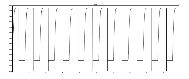
Now, the frequency was about 1.12 Hz, or about 67 BPM. Since the pacemaker was activated, the frequency should have been about 66 BPM as calculated. Again, the simulation was very close to the expected circuit.